|
History:
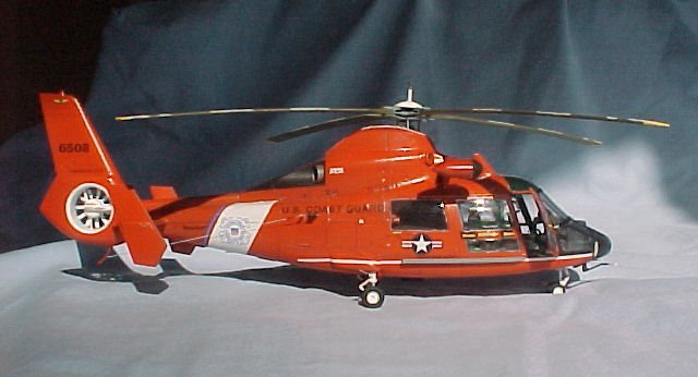
In 1984, the U.S.
Coast Guard accepted the HH65A as an intended replacement for the Sikorsky HH52A
Sea Guard. Designed by Aerospatiale of France (now Eurocopter), the Dolphin is a
modified version of the company's commercially successful AS-365 Dauphin, and is
built in Grand Praire, Texas by American Eurocopter. Used for short-range
recovery, the HH65A has sophisticated avionics, navigation, and communication
packages. This system can bring the aircraft to a stable hover at 50 feet.
Autopilot can perform selected search patterns, freeing the pilot and copilot to
look for the search object. Operating both from shore and Coast Guard Cutters,
the Dolphin is used for search and rescue, drug interdiction, ice breaking,
marine environmental protection and military readiness. When stationed aboard
icebreakers, they are used as the ship's eyes to find thinner and more navigable
ice channels and to airlift supplies to ships and to villages isolated by
winter.
The Kit:
The Trumpeter kit
does a pretty good job of representing a AS-365 Dauphin, however, when it comes
to the HH65A, it has a few shortcomings. Most of these are found in the
interior, but the big error comes from the fact that the AS-365 and the HH65A
use different engines and thus the engine cowling is different. I have also
heard that the HH65A has a larger tail. This is beyond my ability to correct,
perhaps some of the aftermarket guys might consider making replacements. My
focus with this project was not to create a perfect model, but a "more
correct" model.
| As with most
aircraft kits, construction starts with the cockpit/interior, and, as I
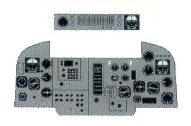
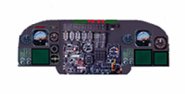
mentioned, this is where the brunt of the changes will occur. Firstly, the
instrument panel is completely wrong in layout and shape. Rather than
build a new "3D" panel, I opted to make a new decal and panel
piece and live with the shape of the coaming. The height of the panel is
different, so its mounting on the centre console must be built up with
plasticard to insure proper alignment. The next area of change are the
seats. The kit supplies two seats for the pilot and co-pilot, and two,
three place bench seats for the cabin area. This may be correct for a
AS-365, but not for an HH65A. The Dolphin only has three seats for the
pilot, co-pilot and rescue swimmer/ winch operator. |
Click on
image directly below to see larger image
|

|
|
|
The rescue swimmer seat is
different in shape than the other two and mounts on a sliding turntable just
behind the flight deck. This seat was made by first cutting the centre section
out of one of the bench seats and sanding the headrest flat. The seat back was
then filed and tapered and a section of headrest from the remaining seat was cut
and glued to the new seat. A piece of wire for the roll hoop completed the
headrest. The seat mounting was made from a piece of 0.020 sheet styrene and
copper wire.
The pilot and co-pilot seats are
essentially correct, however they seem to sit too low and the mounting is solid
rather than the tubular framing found on the prototype. I decided to modify the
mounting to improve both these areas. I also added a piece of styrene for the
bracing on the seat back, and wire for the roll hoop. All seat belts were made
from aluminium foil with Reheat buckles.
The
instruments on the centre console also need to be fixed. There are two CRT
screens missing as well as numerous switches. Reheat CRT's and a flightpath
switch panel from the spares box were added to give this area a better look. Kit
part A5 was replaced by wire and sheet plastic, as the kit offering was too
heavy, although my replacement part is almost as big. A couple of other
switches/handles were also added to this area. The control stick hand grips were
reshaped to more closely resemble the prototype.
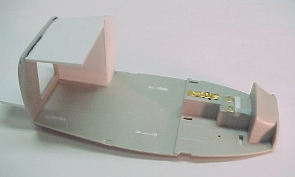
So much for the flight deck. My attention now turned to the cabin area. The seat
mounting slots in the floor were all filled with Tamiya putty and then
correction fluid. Trumpeter has correctly molded the port side of the fuselage
in that a solid panel has replaced the rear window. Unfortunately, they omitted
the avionics bay that occupies this area of the interior. This panel is easily
constructed from sheet plastic, as was the lower ceiling of the rear half of the
cabin. HH65's also have an opening in the rear bulkhead for a storage area. This
was opened up and a deck added. All the dimensions were approximated based on
photos.
The side braces (parts B7 and B10) are not heavy
enough and should extend across the ceiling to the overhead console (also
missing). The photo below shows the original and modified part.
The overhead console
was made by gluing layers of plastic bar stock together and filing it to shape .
Switches and handles were made from wire, while the air vents are drilled
recesses. A lot of test fitting in the fuselage was required to make sure the
instrument panel would line up properly at the top of the windscreen. There are
some details missing, but as it will be barely visible, I wasn't concerned.
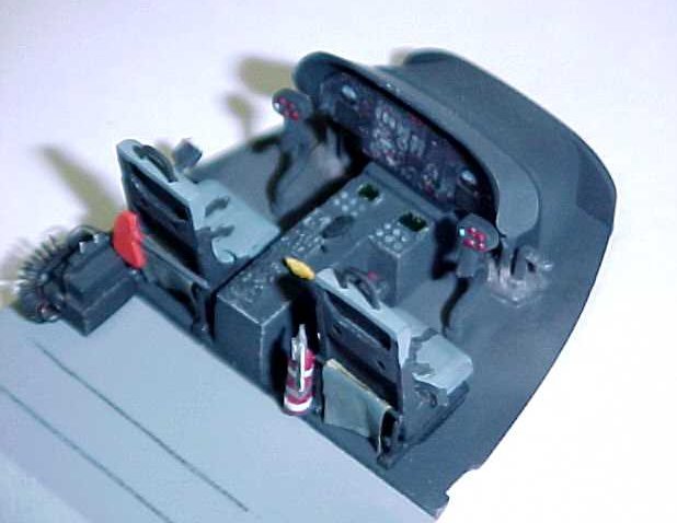
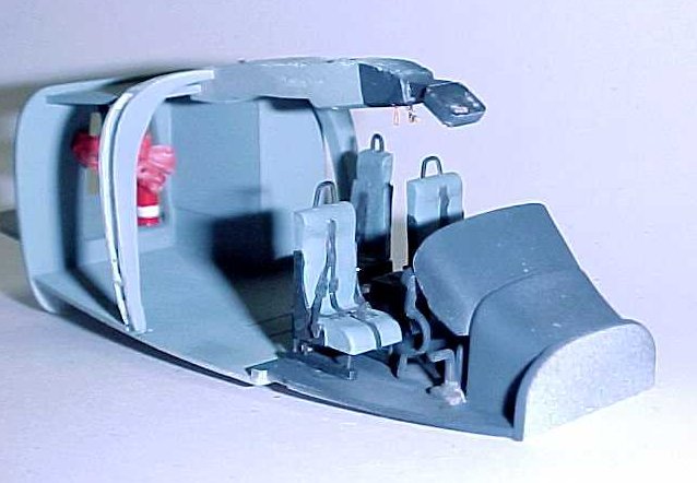
Below are photo’s of the flight
deck and completed interior. I swayed from the instructions slightly by gluing
the braces to the floor rather than to the fuselage sides. I did this to ensure
that the braces connected with the over head console. The pedal mountings were
covered with tissue paper to simulate the boot that covers the linkage. Other
scratch built items include the search light control box, fire extinguisher, axe
and rescue ropes. The interior was lightly weathered with pastel chalks and a
silver pencil.
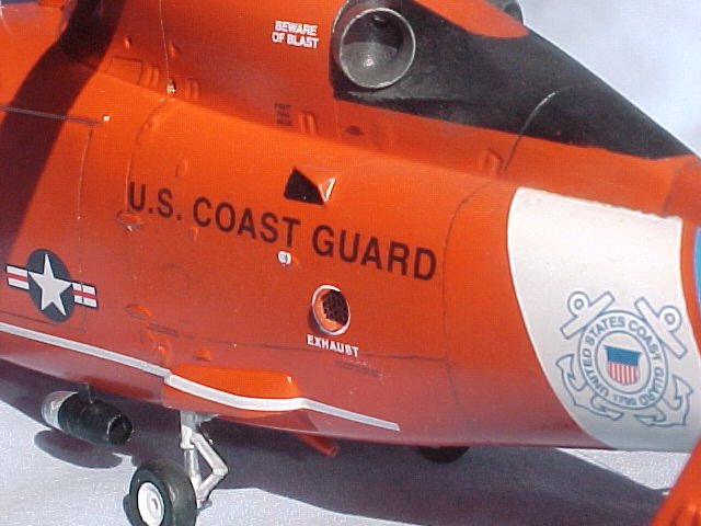
I then masked and
installed the windows in the fuselage halves. These must be masked inside and
out. The windows seams were filled, the interior sides painted and small details
added. The APU exhaust is provided as a decal, so I decided to improve it. The
opening was drilled the appropriate size and sanded to reduce the thickness. A
piece of PE grill was glued to the interior then boxed in and painted dark gull
grey inside. There is a curved air deflector on the exhaust port that was made
by heat smashing a piece of acetate over the head of a #4 screw. It was then cut
to shape and glued to the port. The APU intake fairing was also added from
acetate. The interior was then installed in the fuselage and closed up. The seam
isn't too bad and the soft plastic makes it fairly easy to sand. If I had to do
it again I would remove the locating pins as they caused a bit of a step at the
seam. The pilots door was then removed from the clear nose section and the
missing door seam was scribed onto the co-pilots side. The halves were glued
together and the overhead glazing was sprayed on the inside with Tamiya clear
green. When dry, the part was dipped in future, masked and the interior sprayed
flat black. The masking was removed, grab and door handles were made from wire
and added, and the whole assembly was joined to the fuselage. Remember when I
said Trumpeter had correctly molded the left side of the fuselage. Well, I
wasn't entirely correct. They did blank out the window, but the indent of the
window remained. This area was sanded flush and any damaged panel lines
re-scribed. Some nose weight was added and the bottom of the fuselage closed up.
The fit of the bottom piece is not so good and leaves some rather large gaps.
These were all filled and sanded. The winch operator hatch was then scribed. The
model was then primed and inspected for flaws, of which there were many. After
several Mr Surfacer/primer sessions the fuselage was all tidied up and my
attention turned to the detail free landing gear wells. These were improved with
plastic strips and various diameter wire following photos. The top of the engine
cowl, tail boom and the tail rotor were then painted with Model Master insignia
white with a drop of blue added to it (this is supposed to prevent yellowing).
After that had dried for a couple of days, the white areas were masked off with
Tamiya tape and over spayed with a light coat of future to prevent bleeding.
The tail boom stripe area was then spayed with Model Master French blue
mixed with a few drops of white . Once thoroughly dry, it too was masked off and
coated with future in preparation for the Model Master International orange. I
don't know if it is just me but I feel that color is too orange, so I added a
bit of insignia red (hind sight being 20/20, I should have sprayed the blue
after the orange as I had some trouble getting it to cover). The remaining small
bits (antenna's etc) were added (check your references as some of the antennae
supplied are not used, and some scratch built ones were added) and the model
painted. This is where I ran into a little confusion. Just what color are the
wheel wells? There seems to be 2 or 3 variations. Some Dolphins (early orders I
assume) have outer and inner main gear bays doors with the inside of the doors
and gear bay painted white. Others have the inside of the door white, but the
bay is orange and still others have orange bays and a fairing over the side of
the opening with no doors at all. To make it worse, the gear bay
"covers" supplied with the kit don't match either configuration. They
give you a one piece door or a fairing that is the wrong shape. I opted to
massage the fairing and use it. With that decision made, the orange was spayed.
Once this was dry, the areas that would be black where reverse masked and spayed
flat black. The masking was removed and any touch ups taken care of.
Next was the rotor
assembly. The blades look more like timbers than rotor blades so a little
shaping is required. Once I had achieved somewhat of an airfoil shape the rotors
where sprayed white, masked and tips painted yellow, more masking, followed by
Olive drab. See the drawing below for the stripe measurements (thanks Dale). The
hub was assembled and painted medium gray. The cap had a short piece of
aluminium tubing and brass wire added and was painted white.
I added brake lines
to the main landing gear, flattened the tires slightly and glued them in place.
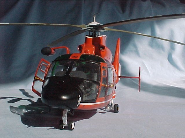
Decals were then
applied. Most of these went on reasonably well although despite my best efforts
there was some silvering. Check your references as I found some slight errors in
the decal placement. The decals for the doors all had the yellow handle area
removed and replaced with ones made from flattened copper wire. The fuselage was
then spayed with Poly S satin finish and the masking removed. The pilot's door
and various antennae were attached and after many months of on and off building
my Dolphin was finally finished.
Special thanks to
Dale Elhardt, who's great photo's and rotor stripe measurements where crucial to
this project, and to Milton Bell, who provided a replacement window when I broke
one while masking.
Lloyd
|
|