|
Continuing
from part I, we go on to detail the wings.
Since the bottom wing part forms the bottom of the fuselage, I detailed the
wings before assembling the fuselage.
The
–4 wing is a little more complicated. When Italeri mixed and matched molds to
produce their line of Corsair kits, they got a few parts mixed up. The kit
has outboard wing pylons that appeared on the F4U-7 or the AU-1. The –4B
had the stub pylons in staggered arrangement that are not included with this
kit. (However, the stub pylons are in the RoG –5 and the Italeri –5N
kits). The –4 had four outboard pylons on each wing. So the kit
parts will work. Open the 4 sets of holes in the outboard wing bottom part. (The
–7 and AU-1 had 5 pylons on each wing. I mindlessly open all 10 sets of holes.
I had to fill in the two outboard pair. Forewarned!) For
the –5N, you only have to open two of the flashed over placement holes called
out in the instructions.
| First
order of business is opening the wheel wells to the wings. Using a
hobby knife, continuously score the edges of the molded detail that
represents the main wheel well detail until you cut through the plastic.
Or, you can carefully grind it out with a motor tool. File the edges
of the hole to smooth the sides and square up the corners. I’m not going
to deepen and detail the forward part of the wheel well. If you do, then
you have to lengthen the main landing gear struts so the model will sit
correctly. (19) |
Click on
image below to see larger image
|

|
|
Place
the wing top on the bottom and trace the gear well hole on the wing top with a
pencil. Using the top of the square as the start line, glue 1.5mm plastic
strips to the bottom of the top wing part to simulate the wing spars. Use
a piece of strip as a spacer to ensure the spars are evenly spaced. When
dry, trim the spars to equal length using the pencil lines as a guide.
Don’t worry about the marred plastic. This will be covered when the gear
well is boxed in. (20)
Before
gluing the wing halves together, we need to open holes depicting 50 cal ejection
chutes on the –4 and open the molded in representation of the 20mm chutes on
the –5N.
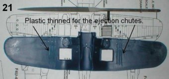
I
drilled out the holes in the –5N wing and squared up the slots with a square
jeweler’s file. The results were not as sharp as I had wanted. The plastic is
too thick. So for the –4 slots, pick off the ejection slot locations from the
–4 drawing and mark their locations on the inside of the wing bottom. Thin the
plastic with a tapered jeweler’s file. The resulting slots will serve as the
chute sides when they are opened. (21)
|
Click on
images below to see larger images
|
 |
 |
Pick
off the location of chute center and open a hole. Using the file, expand
the hole to the correct size rectangle. Go slow. It will be hard to
recover if you get this wrong. Fill in the indentations for the 20mm slots.
(22)
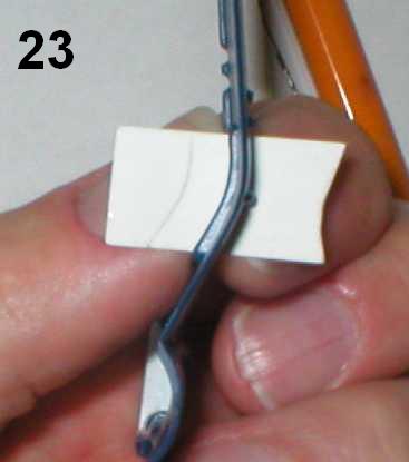
Before
gluing the wings together, cut a strip of index card to width of the main
gear bay. Place the card in the rear of the landing gear hole and trace
the curve of the wing onto the card. This will serve as a template for the
front and back of the wheel well walls. (23)
Glue
the wings together; don’t forget the intake parts in the wing roots. On
the –4, glue the 20mm gun parts in the wing edge hole and cut them off.
When set, fill in any gaps and sand the leading wing edge smooth. (24)
Wait on the –5N 20mm guns. The flash suppressors are fragile. We’ll
add them later.
Using
the template, make 4 sets of the front and back wheel well walls for each model.
Cut rectangle pieces for the wheel sides. Glue the pieces in the well to box in
the hole. Be sure there is excess plastic above the edge. (25)
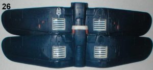
| Cut
down the excess and sand it even with wing; fill in any gaps. I used Mr.
Surfacer and gently sanded it smooth. (26) |
Click on
image below to see larger image
|
 |
|
The
next major wing modification is dropping the flaps. I marked each flap
with a pencil to keep tack of the individual flaps after I cut them out.
Looking down on the wing, I labeled them by the model, left to right, outboard,
middle and inboard. Looking down on the night fighter you would see 5LO
(left-outboard), 5LM (left-middle), 5LI (left-inboard You get the idea.), 5RI,
5RM, and 5RO. Take a hobby knife and carefully and continuously
score the plastic in the groove where the flap meets the wing until you have cut
through plastic. Using a saw cut out each flap. (27)
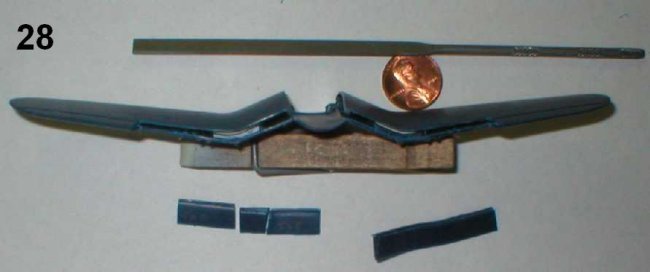
With
a file, square up corners in the wing for the flaps. Using an edge file,
thin the top edge where the flaps fold down. Leave the bottom edge thick;
we’ll use it as a glue surface. (28)
|
Click on
images below to see larger images
|
 |
 |
The
plastic trees in the model kit have two diameters of spruce. Cut a section
of the thin spruce. Using a rattail file, round off the inner edge. Glue
the flap piece to the rod. File and sand to shape. OOPS! I
discovered there is not enough small diameter spruce on the tree to do 6 flaps.
2mm styrene rod works fine. (29)
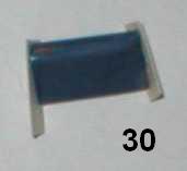
Glue
bits of plastic card to end of the flap pieces to cover the gap. (30)
Fill in the imperfections, and sand to shape. (31)
Oh
goody! Just 11more to go. (Groan!)
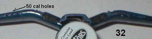
Before
we glue the flaps down, we need to finish up the wing details. For the
–4, to locate the wing edge holes for the 50 cal MGs, draw a line adjacent and
parallel to the inboard edge of the ejection chute to the wing edge. Drill
a 1.5mm hole where each line intersects the wing edge. (32)
Cover
the holes in the wings where the flaps were cut out with plastic card and sand
to shape. (33)
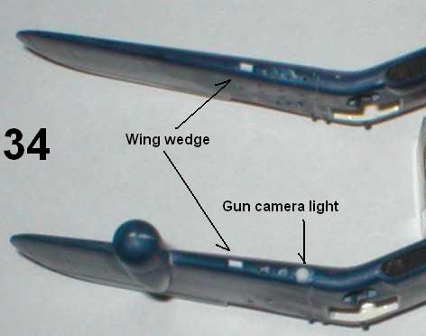
From
the –5N drawing locate the position for the gun camera light on the starboard
(right) wing edge. Drill a 2mm hole and glue a piece of 2mm tubing in the hole.
The end should extend 2mm beyond the wing edge. Don’t forget the radar dome!
Every Corsair had a small wedge on the leading edge of the right wing. I filed
down the corner of a piece of 1mm square rod to fashion a wedge. Glue a 2mm long
wedge piece on the right wing edge 2mm from the outboard gun. (Lots of 2mm
measurements up there. It’s not a SWAG; that’s the way measurements come off
the drawing.) (34)
OOOPS!
I, almost, forgot! On the –4, the right inboard flap had a
rectangle hole that serves as boarding step. Drill a hole in the flap and use a
square file to open it to the correct size rectangle and square up the corners.
I made my step too big trying to square the corners, so I added and sanded down
plastic shims in the top and bottom of the hole to restore the correct size.
(35)
Before
gluing the flaps in place, we need to file notches on the flaps. The notch
locations are not on the drawings, so I eyeballed the size from the detail
pictures in the Detail & Scale book. I filed a rectangle in center of the
top of the outboard flaps, and a square notch on the corners where the center
and inboard flaps meet. Once again, when I filed away too much, I restored
the correct size of the notch with plastic shims and sanded them smooth.
Glue the flaps down in each wing and fill the gaps. (36)
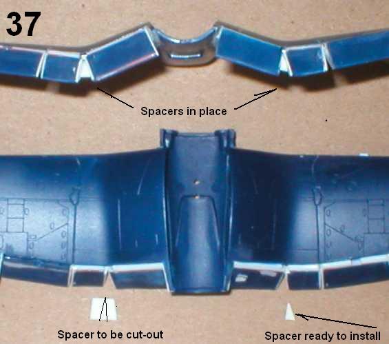
When
Corsairs lowered the flaps a spacer extended to fill the gap between the middle
and inboard flaps. The LAST task for the wing is fashioning these spacers.
Hold a piece of plastic card under the gap and trace the angle. Close the base
to make a triangle about 1/3 of the space from the bottom. Cut out and glue this
triangle in place. Repeat for the other gaps. (37)
You’ll
be tempted to display models of the Corsair wing. Don’t give in!
Hey!
Marty! …. BACK!! TO THE FUSELAGE!!!!!!
|
Click on
images below to see larger images
|
 |
 |
Bibliography:
Decals:
-
F4U-5N:
Super Scale International 72-244 Korean War Aces
-
F4U-4:
Super Scale International 72-700 F4U-4, F4U-5, F4U-5N Corsairs
-
VMFA-312
Checkerboards: http://www.wfix.net/Checkerboards/Main.html
-
Guy
Bordelon
LT/USN: http://www.acepilots.com/korea_bordelon.html
-
F4U-5N
line drawing: http://www.vought.com/heritage/1532_005.jpg
-
Detail
& Scale F4U Corsair (part 2: F4U-4 through F4U-7)
by Bert Kinzey, Squadron / Signal publications, Carrollton, Texas, USA,
1998.
-
Detailing
Scale Model Aircraft by Mike Ashey, Kalmbach Publishing Co, Waukesha, WI,
USA, 1994.
RJ
|