Northrop A9A
History
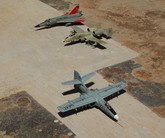
Back in the early 70s there was a time when four attack aircraft prototypes were undergoing evaluation during a 60-day fly-off at Edwards Air Base in California. Identified as a type 2 phase of flight-testing it represented a total of 250 hours on two types, the A10 and the A9 which were showed among five USAF pilots who by the end of the period were each to have flown each type of aircraft for 25 hours.
In task 1, four aircraft (two A-10s and two A9s) amassed some 300 hours of manufacturer’s trials. The joint test force pilots also participated in their earlier trials and were completely familiar with the aircraft types. L. Nelson, the company’s flight test director, flew Northrop’s first A-9A on the 30th May 1972 and 3 months later a second prototype joined the programme. The fly-offs have been conducted on a comparable base with aircraft flying each mission in pairs; one A-9 and one A-10; where assessment attributed to temperature, wind and external factors being the same for both.
In Task 2 each aircraft type had to fly 50 hours on performance testing (which included 6 hours devoted to Systems test), 53 hours on weapons delivery and 20 hours on a Tactical Air Command mission suitability test. The tests conducted included carrying a large war load where special emphases were given upon certain performance parameters equal for both types like serviceability, etc. Other interesting comparison included a 2-hour loiter although not so great distance from take-off, manoeuvrability in achieving a close support aircraft and the USAF asked for an aircraft that could operate under 1,000 ft ceiling in one mile visibility.
Serviceability features were common to both the A-9 and the A-10 designs. Common to both aircraft at the insistence of the air force were redundant control actuation systems to provide back ups in the event of extensive damage, heavy armour plating around cockpit and other vital areas, and self-sealing fuel tanks fitted with surge baffles and plastic foam to minimize fuel loss in case the tanks were holed by ground fire.
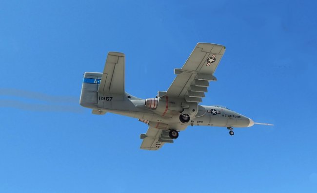
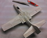
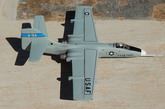
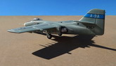
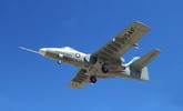
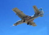
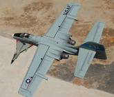
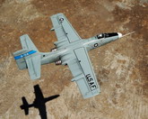
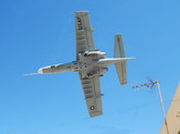
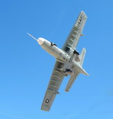
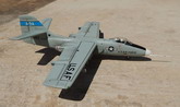
Northrop A9 was a fairly conventional machine, the engines in fairings at the wing root, with a single vertical stabilizer, five stores points on each wing and landing gear that retracted completely. It was powered by a pair of Avco/Lycoming ALF502 turbofans of 6,000 lb thrust each. Had a wingspan of 57 feet, a length of 53 feet 6 inches and a height of 17 feet 10 inches. The two prototypes were assigned the serial numbers 71-1367 and 71-1368.
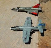
The winner of the production contract for the battlefield anti-tank aircraft was the A-10A, which became known as the Thunderbolt II. Of the two A-9A prototypes built 71-1367 remains in preservation.
|
Click on
images below to see larger images
|
|
|
The Kit
Name: Northrop A9A
Make: Project X Maintrack Hangar Productions
Scale: 1/72
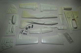
Type: vac-form kit complete with decals and white metal undercarriage, probe and pilot seat.
Cost: 9 Sterling
This is a vac form kit consisting of two white styrene sheets containing all the kit components as fuselage halves, wing and tail plane parts, engine nacelles, engine exhaust outlets, wheel doors, nose wheel well, enough parts to make 10 wing pylons and a clear acetate canopy. A small sealed bag contained the metal parts comprising three metal legs and wheels, nose probe and an ejection seat. 1/72 scale side and front view and a scrap plan view all sufficient for reference during construction of the kit are on one side of the instructions while the opposite side has brief aircraft history, notes to assist in building the model and kit parts exploded view.
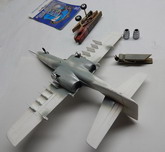
Construction
Kit components were first scored around with a sharp modelling knife and snapped by bending away from carrier sheet around score lines. Any excess plastic was then sanded away and checking with drawing to ensure the amount that should be removed. Revell liquid cement or Humbrol liquid cement could be used to cement parts together. For metal parts Cyanoacrelate (Super-Glue) was used.
Fuselage parts were first prepared, cutting area occupied by gun through on starboard side of nose. On the prototype a long probe was fitted instead. Cockpit bathtub was built from plastic card components as depicted in drawing supplied. Side consoles and pilot instruments were carefully added to the fitted inside the cockpit and a metal ejector seat added in place. Cockpit detail at
the rear of seat was also added and the entire cockpit was painted medium grey while the instruments and seat had touches of black. A crew figure was added to the seat. The cockpit pre-assembly was then cemented onto one fuselage half. Plastic tabs were added to the fuselage edge to serve as guides for the other half. The offset nose wheel well was glued to the port fuselage half. A small compartment to carry nose weight was also built in the nose area. A nose wheel leg hole was drilled inside the nose well roof.
Two splitter plates, flat on both sides were prepared and cemented into position against fuselage sides, ensuring top surface aligned correctly before cementing in place. Wings are cut, sanded and reinforced with cross pieces in between when cementing wing parts together. Cutaways were cut at their root near leading edge. These will accommodate the splitter plates already in place.
Engine bays were then cut and prepared, adding bulkheads within the bays to add strength while the rear ones were to seat the engine outlet pipes. These assemblies were cemented to the wing roots and the fuselage and again making a cutaway in lower surface to accommodate the splitter plates. An item missing from the kit was the front of rotor blades central bullet shaped fairing. This was visible from the outside and had to be scratch built.
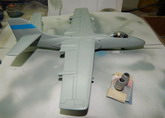
Upper and lower jet exhausts were prepared and cemented centrally into rear engine bay attaching to rear bulkhead. Close study to photos ‘on line’ indicated how far these protruded on the outside. The upper and lower tail plane halves were cemented together and attached to fin. I made a cardboard template to equalize the correct dihedral angle on both sides using the front elevation view depicted on the instructions. The flap guides, four in number, were prepared fresh, as ones given were slightly undersize. These were attached to inner wing fairings. Even the fairings themselves were enlarged, as the ones integrated with the wing trailing edge were undersize and too short. Undercarriage legs added in place and wheel doors glued in place. Cockpit canopy was trimmed with a sharp knife, checked for correct seating and fixed in place using white glue.
The metal nose probe was too small and was replaced with a metal one of correct size. This was fitted to starboard side. 10 bomb racks were finally fixed at equally spaced stations under wings. Through out the construction all panel lines were refreshed with scoring tool as these were lightly marked.