|
Legend
says, that the Boeing 747 was born in private talk of the CEO's of 2 companies: Boeing and
Pan American World Airways (PanAm). We would not discuss if this legend true or
not, instead we will talk about plane and it’s model.
Yes, it’s not legendary the Dakota DC-3, but it is impossible to
not to recognize the characteristic silhouette with its “hump on the back”.
It was the biggest, fastest, heaviest when it was introduced.
Some
of it’s records are still actual today, some were taken by other, newer models,
but it’s still holds it’s own.
Official history of the 747 began on April 13 of 1966, when PanAm
announced an order for 25 airplanes, totaling a staggering $525 million!
The prototype made its maiden flight on February 9th, 1969, and
right after Christmas of the same year (actually, on December 30th) Boeing received
a gift from FAA (not from Santa Claus) in the form of Airworthingness Certificate
for the 747.
The first commercial flight of the new plane, now known as the
“Jumbo
Jet”, was commenced on January 21st of 1970 on the New York – London route.
1970 saw beginning of production of the more advanced model
747-200, and in 1982 the first flight was performed by the model 747-300 with extended
upper cabin.
In 1985 Boeing announced the beginning of development of the new,
modern version of 747.
Version –400 differs from previous (now dubbed
“Classic”) models in having the “glass cockpit” with 6 multifunctional CRT
screens, 2-man crew (position of flight engineer was eliminated). Wingspan was
increased by 6 ft (1.8 meters) and for the first time in the history of plane building,
wings received 6 ft tall (180 cm) winglets. The new model also got new - more
powerful and economical - engines, modified shape of fuselage-wing joint
(remember this!), modified interior of passenger cabin. Structural changes and
wide use of composite materials allowed for a decrease in airframe weight, increasing
MTOW at the same time.
On January 26 of 1988 Boeing 747-400 was revealed to the
public, and took to the air on April 29 of same year. Northwest Airlines was the
first commercial operator with the first paid flight on January 28 of 1989.
In 1989 was build and began commercial operations 747-400
Combi (mixed pax- and cargo- version), and in 1993 Boeing delivered the first
747-400 Frighter.
According to Boeing: «As on May 2006, 41 customer ordered 688
units of 747-400, making this model the most popular widebody plane in a history
». Companies around globe are using the 747-400. Here is a list of operators of
-400:
Passanger:
Aerolineas Argentinas, Air China, Air France, Air India, Air
Pacific, Air New Zealand, All Nippon Airways, Asiana Airlines, British Airways,
Cathay Pacific, China Airlines, Corsairfly, El Al, EVA Air, Garuda Indonesia,
Japan Air Lines, KLM Royal Dutch Airlines, Korean Air, Lufthansa, Malaysian
Airlines, Northwest Airlines, Oasis Hong Kong, Philippine Airlines, Royal Air
Maroc, Qantas Airways, Saudi Arabian Airlines, Singapore Airlines, South African
Airways, Thai Airways, United Airlines, Virgin Atlantic
Cargo:
Air China Cargo, Air France Cargo, Atlas Air, Asiana Cargo,
Cathay Pacific Cargo, Cargolux, China Airlines Cargo, China Cargo Airlines,
China Southern Cargo, Dragonair Cargo, Emirates Skycargo, EVA Air Cargo, Global
Supply Systems, Great Wall Airlines, JAL Cargo, Jade Cargo International, KLM
Cargo, Korean Air Cargo, Martinair Cargo, Nippon Cargo Airlines, Polar Air
Cargo, Singapore Airlines Cargo
Other:
Abu Dhabi Amiri Flight, Boeing, Dubai Air Wing, Government of
Brunei, Government of Japan, Government of Kuwait, Government of Saudi Arabia,
Kingdom Aircraft Leasing, Royal Flight of Oman, United States Air Force
But enough talking, let’s go back to our topic – the model of
this plane.
While in the model shop I passed by a shelf with a pile 747, I
involuntarily took one box in my hands, looked at it, and with very big reluctance
I had to put back - the price of model - 27 dollars – seemed quite high for me.
We
all know, that price alone cannot scare us if we have the “I have to have it!”
urge, but I purchased much more expensive model month ago, and Boeing was put
back, and I continued my path to the clearance table, where I spotted the same model, in
an open box, but for half of the price! Under suspicions that something was missing
inside, box was emptied, and all contents inspected – all parts were still in
plastic bags! Sure enough, I was not able to put this box back, so $13.50 they found
their way from my pocket on another side of counter, and pretty blue box found
its place on… right – on my shelf at home.
For an unknown reason 2006 was the “year of civil aviation” for
me – Concorde then Airbus A-380, and after finishing old Airfix Trident box
with 747 was taken from shelf and placed on my work desk.
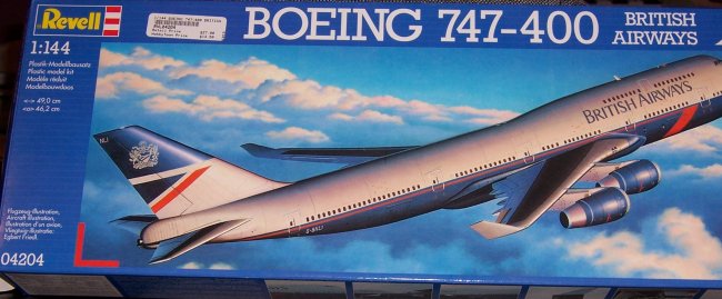
The
box
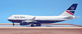
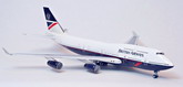
is typical for Revell – without lid, with a drawing of a Boeing 747-400 in the
air, and with pictures of prototype on sides. Inside we can find:
4 sprues with parts, made from white-colored plastic
2 halves of fuselage, made from same plastic
1 small sprue with clear parts (in separate bag)
1 page of decals for 1 aircraft (with label “Printed in
Italy”)
1 instruction booklet with 8 A5-sized pages – 4 pages of
drawings for assembly steps, one page – painting/decal placement guide, one
page – brief history of plane and used colors (only Revell colors given), and
2 pages of warnings.
Plastic is smooth, semi-soft, could be sanded quite easily and
is not brittle.
One part carries the following inscription: «© Revell 1993»,
giving us a clue about age of the mold. For it’s long carreer the mold developed some
wear-and-tear, which is showed in form of some flash here and there, and uneven
panel lines scribing (especially on fuselage). All details molded almost
(let’s remember this word “almost”!) perfect, without caverns and
blemishes. I did not find any injector pin marks on external surfaces. Good!
Click on
images below to see larger images
I
consider myself as a relatively new modeler – a little bit more than a year and a half of modeling, so I am looking on each and every model as a
test field for new (for me) materials, technologies, tools and other
stuff. Because of this I did not think about any improvements for my model
– I planned to do a simple OOB build, without painful comparisons with
drawings, after-market goodies and scratch-built parts.
So, plastic parts taken from the box, instruction
studied, time to start!
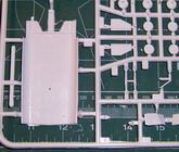
“I started making my model from the cockpit” – I wished
to say, but I realized, that the cockpit does not exist in this model! Which
is quite strange, because the cockpit glass is provided, and if the model
is completed as given, one will be able to see the complete fuselage inside!
Revell didn't even make any divider between the cockpit and the rest of the
cabin. I did not want my plane to look like a shell, so I decided to build
something similar to a cockpit interior. You cannot see a lot in 144-scale,
so I did not spend a lot of time and effort in this venture – 2
half-oval shapes were cut from sheet plastic, adjusted to shape, 2 pieces
of sprue were glued as a support to fuselage halves and half-ovals were
glued in place, representing floor and the rear bulkhead of the cockpit.
I also
glued a small piece of plastic under the cockpit front window, representing
an instrument panel. A little bit of paint hid all the seams, and to fill
this space with something I glued 2 figures to the floor, positioning them
so only the heads and shoulders will be visible from outside. It looked like
this:
Click on
images below to see larger images
|
|
|
initial
version of cockpit |
Then
I decided to bright it up I little, and I decided to paint the upper passenger
cabin in a different color. More pieces of sprue were glued to the fuselage
halves behind the cockpit as an improvised floor support, a piece of sheet
plastic was cut and sized/shaped to represent floor, and when I was ready
to glue the “floor” in place, I noticed, that some windows were closed by
the manufacturer – you could see shapes inside. I took pictures of the real
plane, counted windows and was quite disappointed – 10 windows were
extra, but 13 were missing! So, I cut open the missing ones, and put some
masking tape over the extra ones from outside, I filled them with Squadron
White putty, in hope, that it will form a smooth surface when dry. Wrong!
Removal of the tape the next day revealed a requirement for extra filling/sanding…
- you know the drill. Conclusion: “Study original!” So, the floor is glued
in place and the upper cabin is painted in blue color. What? Why blue? I do not
remember now why blue was chosen, but I think it looks good on BA
aircraft.
At the same time on AircraftResourceCenter - forum (arcair.com)
someone started a topic about “how to light-up aircraft”. Search of
previously posted models there showed, that only handful of models were
“lighted”. But I could not continue to work on my model anymore – it
was so tempting to make it look like a working plane, not just sitting on
tarmac. Then a simple idea “if I would not succeed with lighting, I will
have a regular model” put required balance into my thinking, and work on
the model was resumed and I begun to read all materials on
AircraftResourceCenter about lighting of aircraft. I decided to not to use
incandescent light bulbs, because they could (and will!) burn out.
Instead, I planed to use LEDs (because they do not burn) and fiber optic
cables in place, where LED placement is questionable. For flashing lights
I ordered an “Adjustable Flasher” module, produced by “Fiber Optic
Product”, which allows you to change the frequency and size of impulses. I also
ordered some fiber-optic cables and LEDs of different sizes/colors.
Since the “flasher” requires 9V power, this dictated
the power source for the model – regular 9 Volt battery. Initially I decided to
power it up from outside without extensive modifications to the plane, so
power should be fed into plane thru the undercarriage legs.
I decided to put the following lights into my model: 2
taxi/take-off lights on each wing root, taxi light on nose wheel,
red/green lights on wingtips and white light under APU exhaust pipe on
tail. The idea of installing logo-lights was dropped, because those lights are
installed in the middle of the stabilizer plates, but stabilizers presented in
the kit as a complete halves – left and right.
Dry-fitting the wing halves together I spotted problem area
for lights – wingtips. LEDs were thicker, then the wingtips. I tried to sand
the LED down to acceptable size, and almost succeeded in it – the LED fit
inside, but I managed to break the contact wire, turning the LED into a useless
piece of milky plastic. So, I need to find another way to light it up
(I did not want to use fiber-optic cable, because I was afraid of the amount
of light being passed thru it – to get enough light you have to use tick
fiber-optic cable, which requires more space. If you use thin fiber-optic
cable you won’t have enough light). Solution was found in form of …
broken cell phone. Nokia model 3220 had lit edges on the case, which is
produced by tiny LEDs, soldered to electronics board. Those LEDs are small
(approx. 1.5*0.5*0.5 mm or approx. 1/16*3/64*3/64 in), and do not have
contact wires – they are soldered directly to a board. So, I carefully
un-soldered them from the board, soldered contact wires to them and to create
a strong enough bond between the LEDs and the wires I covered it with CA-glue,
creating quite a strong module. Molded wingtip lights were cut off, channels
for wires were scribed inside of wing halves and the wing was assembled with
clear tape to hold it in place for a test.
Click on
images below to see larger images
|
|
|
wing
lighted |
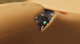
The main cabin
should receive light from 6 white LEDs, mounted inside on piece of sprue.
Doing this I realized, that I can “put some light” inside of cockpit
and “light up” instruments on the panel. I removed a recently glued solid
“instrument panel”, and replaced it with piece of clear plastic, with
several dots of different bright colors (red/green/yellow/blue) with dark
gray paint covering rest of it. Light is coming thru those color spots
from an LED in the nose part of passenger cabin.
|
Click on
image below to see larger image
|
 |
|
cockpit
lighted |
|
To
prevent light bleeding thru plastic, the fuselage was painted flat black inside.
After several dry-fit attempts, the fuselage halves were clued together using Tenax
R7 (great stuff!), and CA -glue was poured over seams to increase structural
stiffness. To increase the stiffness even more and to prevent light bleeding thru
the seams, I glued strips of metal foil over the seams. Regardless of the age of the mold,
the halves joined almost perfectly.
After joining wing halves I was quite disappointed – the size
and shape of the halves were the same, but the trailing edge was way out of scale –
about 2 mm (3/32 in) – which is about 30 cm (1 feet) in real size (from
144-scale). I tried to sand off the extra plastic from inside of wing halves, but
I had to do it on the outside surfaces too. I drilled additional holes in the corners of
the wheel wells on the wings and ran wires thru them – one per wing.
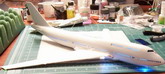
Here you can see how it looked, when I attached thewings to
the fuselage with tape. Looks good to me!
Click on
images below to see larger images
|
|
|
wings
attached to fuselage first time |
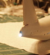
For
the white tail light I used 3-mm (1/8 in) fiber-optic cable, attached to an LED inside
the fuselage. LEDs for upper and lower flashing lights were firmed with CA-glue,
sanded to shape and glued in place.
Click on
images below to see larger images
|
|
|
|
|
Tail
light |
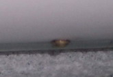
|
Top
flasher
|
Wings
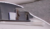
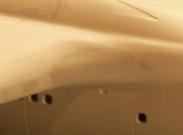
were attached to the fuselage using CA-glue, and work stopped… Something did not
look right! If you recall from description of the difference between the 747-400 from
previous versions, one of differences is the different shape of the wing/fuselage
fairing. Revell probably made the first model –200 or –300, and then for the
model
–400 they decided to “patch” this fairing. Here is how it looks “Revell
style” and how it looks after putty and sand paper.
Click on
images below to see larger images
|

|
|
|
|
wing
root problem |
|
re-countered
wing root |
Conclusion
number 2: “Study information from independent sources!”
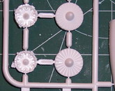
Now it was time for the engines, which are 4-part assemblies.
The edges of the cowlings are a little bit under-molded creating triangle-shaped
notches, which is quite hard to fill, because of the small contact area. Automotive
filler “Bondo” worked perfectly here and it is my filler of choice now!
Click on
images below to see larger images
|

|
|

|
|
engine’s
problems |
|
engine’s
problems fixed |
After
the wings were glued in place, my model was primed with Tamiya White Primer, exposing
some problem spots, but hiding all putty spots! Problems were reworked, a new
layer of Primer hides the repair patches and after 2 days of drying time, my model
was sent to the “paint shop” were it received several layers of Tamiya white
acrylic paint. Then work continued on the following tempo: 2-3 hours of masking,
painting, 5 minutes to un-mask, 2 days of drying time, and let’s start again.
In a week all 4 main colors were “in place” and I got a tough question to
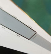
answer: what to do with the leading edges? On a real plane the leading edges of
the wings/stabs/tail are unpainted and have the color of polished aluminum.
So, if they should have color of polished aluminum, why not to
use aluminum? I decided to try another “new” for me – BMF. The leading edges
of the wings/stabs/tail are covered with ModelMaster’s self-adhesive foil. This
foil is very thin and requires a lot of accuracy and patience, but the end result
is worth it! Since ModelMaster’s foil is quite expensive, I wanted to try a cheap
alternative – kitchen foil. Kitchen foil is much thicker, bit in some cases
it’s a big plus – on double-curved plates. And planes have a lot of them! To
work with kitchen foil I used special solution from “MicroScale” – Micro
Metal Foil Adhesive. I spread the solution over the foil, waited a couple of minutes,
until the solution changes color, and then use it as regular self-adhesive foil. Highly
recommended! So, after I realized that kitchen foil is a good modeling material, I
covered the engine pylons with it!
Decal time! Before decaling my model was sprayed with Future,
creating a smooth gloss surface to prevent silvering. Unfortunately, the decals in the
kit are not the best. For me they are quite thick, but they react to several
applications of MicroSol/MicroSet. (I like decals for Revel’s Airbus A-380
better). I did a stupid mistake during painting, making some decals unusable –
the upper fuselage of the plane was painted in a light-grey color, but looking
at photos
of the plane on Airliners.net, It looked white to me, so I painted the top of
the fuselage in white color. This made it impossible to use door-frames decals from
kit – they are white too. So, I ordered a decal kit “Boeing 747-400 doors and
windows” from DrawDecals. Decals came by mail in 3 days and were placed on my
model the same evening. Decals are perfect quality – very thin, crisply printed.
The instructions recommend covering with sheet with layer of Future before use, to
prevent destruction of the decals during their application.
Click on
images below to see larger images
|

|
|
|
|
Decals |
When it was time to attach
engines to the wings I realized, that alignment pins on wings were too small, to
provide good attachment points, so I cut them off, drilled holes in wings
instead and glued pieces of thick wire (paper clip) into it. This worked
perfectly!
Illuminators
were made using Testor’s white glue. (Dip toothpick into a puddle of glue,
transfer it into hole, spread it over all edges and remove toothpick from the center, creating
a thin layer. Did it? Now repeat it 187 times more)
Now - back to “paint shop” for another layer of Future.
So, the model is quite close to being finished; now it’s time to
“put it on its own legs”. As usually with 144-scale models, undercarriage is
quite schematic, presenting only main structural components. My Boeing 747 was
given 4 main “legs” with 4-wheeled boogies each plus nose leg with 2 wheels,
so be patient during painting 18 tires and disks. After I glued all the legs into
place, I was quite disappointed realizing, that 1 “leg” is shorter, than
required and “in the air”. Unfortunately, I cannot expand plastic, so this
leg should be broken and extended, using plastic or metal tube. Wheel wells
doors are un-proportionally thick, but I was afraid to thin them down and glued
them in place as is.
Electrical wires, protruding from the wheel wells were stripped
from insulation and glued to undercarriage legs using CA-glue, imitating pipes
of hydro-system. For electrical contact I glued wire to bottom of the buggy,
making several back-and-forth passes between front and rear wheels.
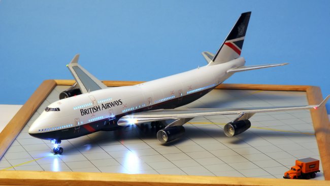
Done! My model is ready, but it cannot be displayed – I have to
make a stand.
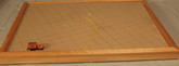
From one of my previous projects I got a wooden photo-frame,
sized 54x44 cm (21x18 in), and I decided to use it to create a “piece of
tarmac”.
Since all control surfaces on my model in the closed/neutral
position, I dropped the idea to put my plane on a runway – it would look good, but
unrealistic. So, I decided to put my model on a tarmac “going to the gate”.
In the home improvement store I purchased a leftover piece of thin
laminated cardboard. I scribed the plastic side, imitating concrete plates, and then
sprayed it with gray paint. The next day I put on some masks and painted yellow lines,
making centerlines. Now – I highlight the scribed lines with a black marker and
it was done! The tarmac was ready! When I tried to install a battery under this piece I realized
that the frame was too shallow – I need more depth. Back to home improvement store,
searching for wooden plank of the required size and color. After an hour of work with
a saw, drill and screws it was done – battery holder securely attached to wooden
frame, and a strip from Erector set holds switch to turn it on and off.
Click on
images below to see larger images
|
|
|

|
|
base |
|
bottom
of the base – wires |
To
transfer the electrical power into my model I cut 2 pieces of metal square-shaped pipe,
a little bit shorter then buggies, and soldered wires inside of them, I glued
those pieces into previously defined places on my tarmac. The wires were out thru it
right there, so you cannot see the wires at all. Then I decided to eliminate the
switch,
because I was afraid that switching it on and off might bounce the whole frame and
damage model. So, I bought a small reed-relay, removed the coil from it and what was
left was a magnetic contact, which was glued under the “tarmac”. In a train store I
purchased truck in 160-scale, detached the cargo compartment, glued in my strongest
magnet and re-attached the cargo compartment back.
Now I do not have to reach for switch hidden under base –
all I have to do is just roll the track on it’s own wheels. The magnet is quite strong
and contact is quite sensitive to create several square centimeters area so, I
do not have to search for exact location – it’s right there – in a corner.
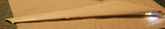
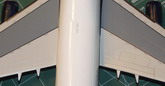
I thought that work on model is done, but a more experienced
friend pushed me quite hard to make it right – so I learned another new
technique – washing panel lines. Wow! What a difference it makes! Look for
yourself:
Click on
images below to see larger images
|
|
|
panel
lines |
Panel
lines on left wing already washed, on right wing – not yet. Many Thanks to
Yuval Kizner for his persistence.
So, is the work on model done now? Not quite yet – now it’s
time to show my model! And here friends come to my rescue! Many Thanks to Roman Naumov
for his skills and patience taking pictures of model.
Click on
images below to see larger images
Now I can summarize my
experience:
It took me 4 months to finish this model, working at my own
pace.
I learned how to work with foil, how to wash panel lines, how
to use information before work, not during, but most important – I got so much
fun doing it!
Leo
|
|